

 English
 Español
 Русский
 العربية
 Français
 Deutsch
 Português
 Tiếng Việt
 ไทย
 Bahasa Indonesia
 Türkçe
 Italiano





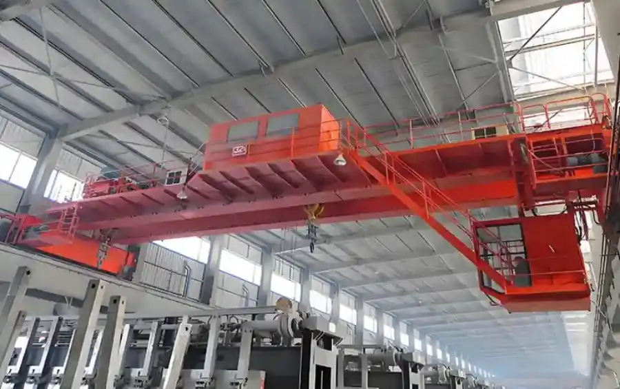
An insulation overhead crane is a purpose-built lifting system engineered to operate safely in environments where the load, the surrounding equipment, or both carry lethal levels of electrical current. Unlike a standard overhead crane, this product is not simply a bridge crane with extra paint or a thicker cable. It is a structurally insulated machine designed to prevent current from passing through the crane's metal framework — a failure mode that would instantly electrify the entire structure and pose a fatal risk to operators and ground personnel.
The defining application for this product is the potroom of non-ferrous metal smelters: electrolytic aluminum, magnesium, lead, zinc, and copper plants. In these facilities, electrolytic cells carry direct currents ranging from 60 kA to over 500 kA, and the potline generates intense magnetic fields. A standard crane operating in this environment would become a current path the moment its hook or wire rope contacted a charged anode, busbar, or molten metal ladle. The insulation overhead crane is the only engineered solution that breaks that path reliably.
Why Standard Cranes Cannot Operate in Potrooms?
The operating environment of an electrolytic smelter presents three simultaneous hazards that a conventional overhead crane is not designed to withstand:
High-current electrical exposure. Electrolytic cells operate at tens to hundreds of kiloamperes of DC current. Busbars, anode assemblies, and cell shells are routinely energized. If a standard crane's hook contacts any of these, current flows through the wire rope, into the hoist drum, through the trolley frame, into the bridge girder, and down the end trucks to the runway rail — electrifying every conductive surface in the path.
Strong magnetic fields. Potlines generate magnetic fields up to 0.05 T or higher. These fields induce eddy currents in ferromagnetic crane components, causing unexpected heating, torque on the hook block, and uncontrolled hook swing. Standard hooks and sheaves made from carbon steel are magnetically susceptible and become safety liabilities.
Corrosive and high-temperature atmosphere. Smelting workshops combine ambient temperatures of 50°C or higher with aluminum oxide dust, carbon dust, graphite particles, and corrosive gases such as hydrogen fluoride. These contaminants penetrate standard electrical enclosures, degrade insulation layers, and accelerate structural corrosion.
An insulation overhead crane addresses each of these hazards through a layered design approach, not a single add-on component.
Triple Insulation Architecture: The Core Safety System
The technical foundation of an insulation overhead crane is its triple insulation barrier system. According to Chinese national standards for insulated cranes (TSG 51-2023 and JB/T 8907-2013), a qualified insulation overhead crane must incorporate three independent insulation stages, each physically separating a segment of the load path from the crane structure.
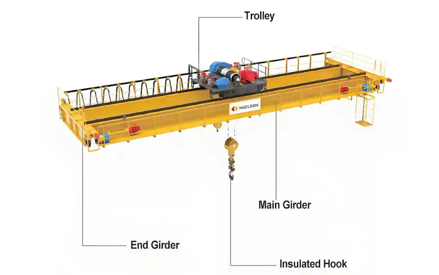
First barrier — Hook to movable pulley block. This is the most critical insulation point because it is the first interface between the charged load and the crane. An insulated coupling is installed between the hook crossbeam and the pulley block frame, using high-performance dielectric material such as epoxy phenolic glass cloth board. This barrier blocks current from entering the wire rope and traveling upward into the hoist mechanism.
Second barrier — Hoisting mechanism to trolley frame. Even if the first barrier is compromised, the second barrier prevents current from reaching the trolley's structural frame. The hoist mounting interface incorporates an insulated plate or sleeve assembly that electrically isolates the entire hoisting unit from the trolley chassis.
Third barrier — Trolley frame to bridge girder. The final barrier isolates the trolley assembly from the main bridge structure. Insulated wheel assemblies or insulated rail pads are installed at the trolley-to-bridge interface, ensuring that no current path exists between the trolley and the crane's main girders or runway system.
Each insulation barrier must achieve a minimum resistance of 1.0 MΩ when measured at 20–25°C with relative humidity ≤85%, tested with a 1000V megohmmeter. This is not a one-time factory test — the standard requires continuous insulation monitoring systems with automatic audible and visual alarms that interlock with the main power supply. If any barrier's resistance drops below the threshold during operation, the system alarms and can power automatically.
Anti-Magnetic and Anti-Sway Design
Beyond electrical insulation, the potroom's magnetic field demands specific mechanical design choices. Standard carbon steel hooks experience magnetic attraction forces that cause the hook to drift, swing, or rotate unpredictably during lifting — a serious hazard when positioning anodes or tapping molten metal.
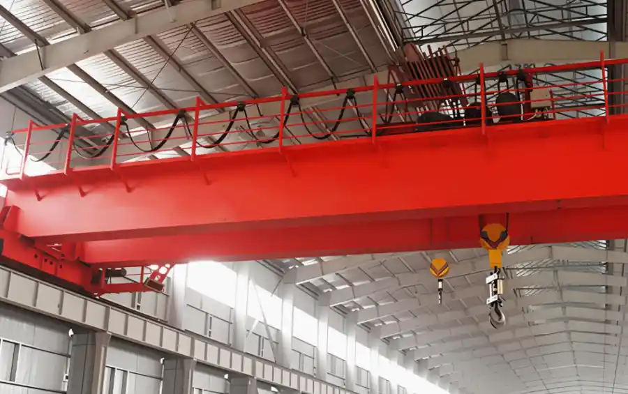
Insulation overhead cranes use non-magnetic or low-magnetic hook assemblies, typically fabricated from austenitic stainless steel grades such as 1Cr18Ni9Ti, which are inherently resistant to magnetic induction. The pulley block, hook crossbeam, and associated rigging are similarly specified in non-magnetic materials to eliminate eddy current heating and magnetic torque.
For applications requiring precise positioning — such as anode setting, aluminum fluoride feeding, or molten metal tapping — rigid guide frames or anti-sway mechanisms are integrated into the trolley design. These systems physically constrain hook movement, reducing the operator's reliance on skill alone to manage load swing in a magnetically active environment.
Electrical System Protection
The electrical system of an insulation overhead crane requires protection far beyond standard IP ratings. Potroom dust is conductive, and corrosive gases degrade standard enclosure seals within months.
-Enclosure rating: Electrical cabinets, motor junction boxes, and control panels should be rated IP55 or higher to prevent ingress of conductive dust and moisture.
-Cable specification: High-temperature, chemically resistant cables with reinforced insulation are used throughout. Festoon cable systems or conductor bar supplies must be specified with heat shields if installed near hot cell lines.
-AC/DC isolation: The crane's AC power system and the potroom's DC environment must be effectively isolated. Control circuits typically operate at 36V or 24V for personnel safety, and all control devices feature dual-step emergency stop functionality.
-Continuous insulation monitoring: As noted above, an onboard insulation resistance monitoring system provides real-time feedback on the integrity of all three insulation barriers, with alarm interlocks tied to the main disconnect.
Procurement Specification Checklist
When sourcing an insulation overhead crane, buyers should provide the following data to ensure the supplier delivers a product that matches the actual potroom conditions:
-Lifting capacity (main hook and auxiliary hook, if applicable)
-Span (center-to-center distance of runway rails)
-Lifting height (rail top to hook center, maximum)
-Working class (A6 minimum for potroom duty; A7 for continuous multi-shift operation)
-Insulation resistance requirement (confirm 1.0 MΩ per barrier at 20–25°C, ≤85% RH)
-Insulation monitoring system (continuous monitoring with alarm interlock — mandatory per TSG 51-2023)
-Hook material specification (non-magnetic stainless steel for potroom applications)
-Electrical enclosure rating (IP55 minimum; IP65 for high-dust zones)
-Power supply (voltage, frequency, phase — e.g., 380V/50Hz/3-phase)
-Control method (insulated cabin with climate control is standard; pendant or remote control is generally not suitable for potroom use)
-Corrosion protection (epoxy zinc-rich coating, stainless fasteners in critical areas)
-Ambient conditions (maximum temperature, dust type, presence of HF or other corrosive gases)
-Special functions (anode handling, aluminum tapping, fluoride feeding, integrated weighing)
For electrolytic aluminum plants, consider specifying an insulated feeding crane variant that integrates aluminum fluoride feeding, anode handling, and molten aluminum extraction into a single machine with an electronic weighing system for process control.
Installation and Commissioning Considerations
Installation of an insulation overhead crane requires attention to details that are irrelevant for standard cranes:
-Runway rail grounding: The runway rail system must be properly grounded to provide a safe discharge path for any stray current. Insufficient grounding can cause voltage buildup on the rail, creating a shock hazard for maintenance personnel.
-Insulation barrier verification: Each of the three insulation barriers must be tested on-site with a 1000V megohmmeter before commissioning. Test records should be retained as part of the crane's permanent safety documentation.
-Bolt anti-loosening measures: Vibration and thermal cycling in potrooms accelerate bolt loosening. All structural and insulation mounting bolts should use verified anti-loosening methods (e.g., Nord-Lock washers, thread-locking compound, or double-nut configurations).
Load testing: Static load test at 1.25× rated capacity and dynamic load test at 1.1× rated capacity must be performed per applicable standards before handover.