
 English
 Español
 Русский
 العربية
 Français
 Deutsch
 Português
 Tiếng Việt
 ไทย
 Bahasa Indonesia
 Türkçe
 Italiano





The wall mounted jib crane is a specialized material handling solution designed to utilize existing vertical infrastructure—such as steel columns or reinforced concrete walls—as the primary support structure. Unlike floor-standing jib cranes that require dedicated foundations and occupy valuable ground space, this system transfers all operational loads directly into the host building structure. This makes it the definitive choice for congested workshops, assembly cells between machinery, or loading bays where floor space is at a premium.
However, the efficiency of a wall mounted jib crane comes with strict engineering prerequisites. Because it lacks an independent base, its safety and performance rely entirely on the structural integrity of the mounting surface and the specific mechanical configuration chosen.
Tie-Rod vs. Rigid Mast: Selecting the Right Support Mechanism
The most critical technical decision in specifying a wall mounted jib crane is choosing between a tie-rod design and a rigid mast (cantilever) design. This choice dictates the load capacity, rotation range, and structural demands on your facility.
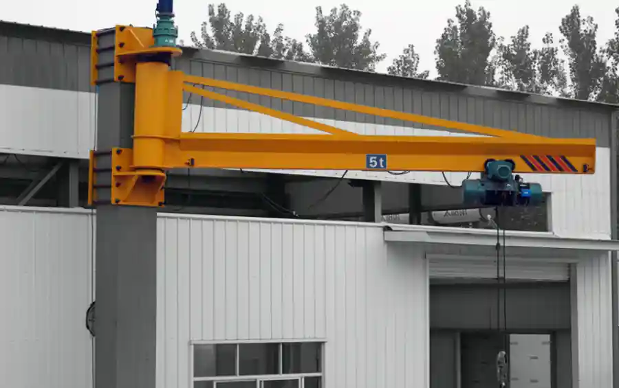
•Tie-Rod Design: This configuration uses a diagonal tension rod connecting the outer end of the boom to the upper mounting bracket. The rod handles the tensile forces, significantly reducing the bending moment on the boom and the wall anchors.
◦Advantages: Allows for longer spans (typically up to 6-8 meters) and higher capacities with a lighter boom profile.
◦Limitation: The tie-rod physically obstructs the upper quadrant of the rotation arc. While the boom can rotate 180°, the effective working area is reduced because the load cannot pass through the plane of the tie-rod.
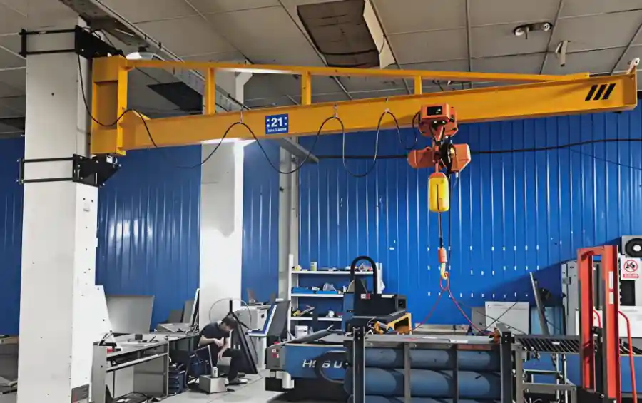
•Rigid Mast (Cantilever) Design: This design relies solely on the structural rigidity of the boom and the strength of the wall anchors to resist bending moments. There are no diagonal support rods.
◦Advantages: Provides unobstructed 180° rotation (or up to 360° if mounted on a corner column with a specialized slewing unit). Ideal for applications requiring precise positioning over a full semi-circle.
◦Limitation: Requires a much heavier, deeper beam section to prevent deflection. Capacity and span are generally lower than tie-rod equivalents for the same wall strength.
Structural Integrity and Load Path Analysis
A wall mounted jib crane does not just lift weight; it exerts massive leverage forces on the building. Procurement teams must validate three specific load vectors before installation:
1.Vertical Shear: The direct weight of the crane plus the lifted load.
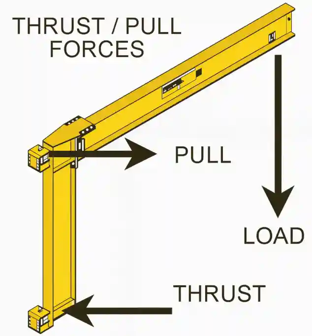
2.Horizontal Radial Force: Generated during slewing (rotation), especially when starting or stopping the swing. This force pulls the anchors horizontally out of the wall.
3.Overturning Moment: The product of the load radius and the weight. This creates a “pull-out” force on the top anchors and a “compression” force on the bottom anchors.
Critical Note: Standard masonry or thin-gauge metal siding cannot support these loads. The crane must be anchored to primary structural steel columns or reinforced concrete walls. If mounting to a steel column, the column’s flange thickness and web stability must be verified by a structural engineer to prevent local buckling under the crane’s point loads.
Rotation Limits and Slewing Mechanisms
While often marketed as “180° cranes,” the actual usable rotation of a wall mounted jib crane depends on the physical interference of the mounting brackets and the building geometry.
•Standard Wall Mount: Typically limited to roughly 180° due to the physical stop of the boom hitting the wall or column face.
•Corner Mounting: When installed on an external corner of a building or column, specialized slewing bearings can allow for nearly 360° rotation, effectively turning a wall crane into a quasi-pillar crane without floor space usage.
•Slewing Drive: For capacities above 2 tons or spans over 5 meters, manual pushing becomes difficult due to inertia. Geared slewing drives with hand chains or electric motors are recommended to ensure smooth operation and precise load spotting.
Installation Prerequisites and Anchor Specifications
Installation errors are the leading cause of wall crane failure. The anchoring system is the single point of failure.
•Anchor Type: High-strength chemical anchors or through-bolts with large backing plates are standard. Expansion anchors are generally discouraged for dynamic lifting loads due to the risk of loosening over time from vibration.
•Backing Plates: Essential for distributing the concentrated load from the anchor bolts across a wider area of the host column or wall, preventing local deformation.
•Deflection Check: Even if the wall holds the weight, excessive flexibility in the host structure can cause the crane boom to “bounce” or drift when loaded. A stiff structure is required for precision lifting.
Procurement Checklist for Engineers
When requesting quotes for a wall mounted jib crane, provide the following data to ensure accurate engineering:
1.Host Structure Details: Material type (steel/concrete), dimensions (flange width/thickness or wall thickness), and age/condition of the building.
2.Clearance Requirements: Height under boom needed for the tallest load + rigging.
3.Coverage Area: Exact radius required and any obstructions (pipes, conduits, other machines) within the swing zone.
4.Duty Cycle: Frequency of lifts per hour. Wall cranes are often used for intermittent service (H3/H4), but high-frequency applications require heavier duty components.
Frequently Asked Questions
Q1: Can I mount a jib crane to any existing steel column?
No. Not all steel columns are suitable. The column must have sufficient flange width and thickness to accept the mounting bolts without local buckling. Lighter gauge columns or those already carrying significant axial loads may require reinforcement plates or a dedicated support frame. Always consult a structural engineer before proceeding.
Q2: What is the maximum rotation angle for a wall mounted jib crane?
Standard wall-mounted cranes typically offer 180° or 270° rotation. Achieving full 360° rotation on a wall-mounted unit is mechanically complex and expensive, as it requires a slewing ring bearing rather than simple pivot pins, and the host structure must be designed to handle torsional loads in all directions. Most applications are adequately served by 180°.
Q3: How does a tie-rod design affect my usable headroom?
The tie rod runs diagonally from the outer tip of the jib back to the wall. This physical bar occupies vertical space beneath the jib beam. Depending on the span and geometry, this can reduce your usable hook height by 300mm to 600mm compared to a rigid mast design. If you need to lift loads close to the ceiling or over tall machinery, verify the tie rod clearance carefully.
Q4: Are wall mounted jib cranes suitable for outdoor use?
They can be, but with caveats. Outdoor installations expose the wall anchors and slewing mechanisms to weather, accelerating corrosion. More importantly, wind load becomes a significant factor. The crane must be rated for the specific wind zone, and a rail lock or brake is essential to prevent the boom from swinging uncontrollably when not in use. The host structure must also be evaluated for combined crane + wind loads.